AT 209 Lab 5 - ULTRA Inspection
Windracers is a UAS manufacturer hailing from the UK. Their main product is the ULTRA, which stands for Uncrewed Low-cost TRAnsport. The ULTRA is a twin engine fixed wing UAS, designed as a low cost self flying cargo platform, able to carry a payload of up to 100 kg for 1000 km and with a heavy focus on redundant systems to reduce risk as much as possible. One of it's hallmark technologies is its Masterless Advanced Autopilot, giving the ULTRA an extremely high level of autonomy. (https://windracers.com/drones/)
Windracers has partnered with Purdue's Center on AI for Digital, Autonomous and Augmented Aviation (AIDA3) for the purpose of research and development for the US market. Due to the different UAS regulations in the US and the UK, they have to modify the platform to meet FAA requirements. This partnership serves as a testbed to achieve this, operating out of Jasper County Airport under the supervision of members of Purdue and Windracers. AIDA3 itself aims to pave the way to "apply artificial intelligence and machine learning (ML)" to make commercial UAS platforms "safe, efficient and scalable" (https://www.purdue.edu/newsroom/2024/Q2/purdue-launches-worlds-first-center-pioneering-use-of-ai-to-innovate-tomorrows-modes-of-autonomous-aviation-transportation/).
The ULTRA operates out of Jasper County Airport. Due to it's operations and size, it must operate outside of Part 107. It is essentially treated like a manned aircraft, weighing in at 300kg. This is considerably lighter than most manned aircraft but well over the 55 lb limit set by part 107.
Our first experience with the ULTRA was to go through a pre-flight inspection. Inspections and maintenance are important for all aircraft, all the way from an sUAS to the largest manned aircraft. "Without regular inspections and maintenance, airplanes run less efficiently. This causes extensive wear on their parts and components which can lead to major problems down the line. Inspection is an important part of maintaining your plane in peak condition. It keeps your passengers and crew safe and helps you avoid unnecessary repairs" (https://republicjetcenter.com/the-role-of-aircraft-inspection-in-aviation-safety/). It is especially important for something like the ULTRA, which needs to be constantly inspected to ensure it's airworthiness in order to advance into the further stages of integration into the NAS. Not only that, Windracers and the ULTRA essentially act as representatives vouching for the future of UAS and UTM, so every precaution must be taken to prevent accidents and incidents, especially if they could've been avoided with proper maintenance habits.
When it comes to doing inspections on the ULTRA, the place to start is the work cards. Work cards cover all the material for taking care of the ULTRA, including inspections, part replacements, and complete overhauls, and are broken down into many categories. A pre-flight inspection falls under a Level O inspection (INS), which is the most accesible level for a work card. Other examples of Level O inspections include an inspection for flights in precipitation and an inspection after a hard landing. There are also various Level O work cards for Line Replacement Units (LRU), Normal Operation (NOR), Troubleshooting (TRB), and Setup (SET).
Inspection Process
Engine:
Check the propellor and spinner for wear and damage like nicks, cracks. Make sure the spinner is not contacting the propellor and the prop spins freely. When spinning the prop, treat it like the engine is live, so you don't loose a hand in case the engine kicks on. Figure 1

Figure 1: Propellor and spinner check
Check the propellor bolts are torqued to 12 nm and check the torque marks. For this, we checked to see that the witness mark is aligned. Figure 2
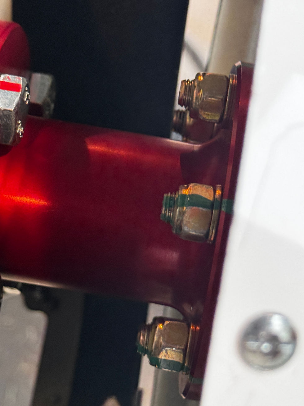
Figure 2: Propellor bolts. Exemplifies how the witness marks work, as they show whether the bolts have loosened, tightened, or remained the same since initial torquing
Inspect the flywheel for damage, condition of teeth, and magneto clearance. Figure 3

Figure 3: Flywheel, magneto, teeth, and starter gear
Check the air filter for cracking and damage.
Check the condition of governor spring: damage, integrity, elongation.
Check the exhaust for damage, cracks, leaks, torque marks.
Check fuel hoses for clearance, signs of chafing, kinks, cracks, leaking.
Check electrical wiring for chafing, damage, signs of burns.
Check the firewall connectors.
Check the motor mounts for integrity, chafing, wire fraying, crimping, torque marks. Figure 4

Figure 4: Motor mounts and other parts of the engine bay.
Check battery voltage, ensure > 12.65 volts.
Check the battery connections are secure and covered.
Check the oil level via dipstick, ensure oil level falls between the drill marks.
Check engine cowling torque marks and inspect for any damage.
Close the engine cowling cover and ensure all quarter turn fasteners are secure.
Undercarriage:
Check tire(s) condition and pressure: cracking, flat spots, 28-30 PSI.
Check torque marks on tire bolts.
Check shock absorbers for leaking, damage, cracks, aligned torque marks.
Check brake disks are clean, floating, undamaged, bolts tight.
Check brake hose for leaks, damage.
Check break pads for damage and wear level.
Wings:
Check electrical connections, vents, fuel hose all connected and secure.
Check structural pins are in place and secured with R pins.
Check wing strut bolt is torqued to 16 nm. Must use a wrench to hold the bolt as the nut is tightened. Figure 5.
Figure 5: Numerous images showing the torqing process for the wing strut
Check fuel content and quality, use the sump to get a fuel sample and examine. For example, gasoline will float on top of water, so the sump will reveal if any water is in the tank.
Check breather vent is secure.
Check for damage on the wing skin.
Check for damage and torquing on the wing strut.
Check the lights for damage and any condensation inside.
Check the pitot tube for any damage or obstructions.
Check the control surfaces for damage and ensure linkages and bolts are tight.
Check the wing root and wing strut fairing: bolts are secure and fairing is not loose/making contact with surfaces it should not be in contact with.
Vertical Tail:
Check the boom for damage, scratching, and corrosion. Ensure the connection to the fuselage is secure.
Check the vertical tail skin for scratches, damage, and corrosion.
Check the control surfaces for damage and ensure linkages and bolts are tight.
Horizontal Tail:
Leading edge bolts torqued to 8 nm.
Main spar bolts torqued to 10 nm.
Check that all connectors are securely attached, making sure that the Amphenol connectors have been screwed shut correctly. Check looms are secure and there is no chafing on the wiring.
Check that the camera is secure and connected to the cable.
In our case, there is no camera.
Check the horizontal tail skin for scratches, damage, and corrosion.
Check the tail tips for damage and paint discoloration. Additionally, ensure the antennas are secure and in the correct position.
Check the control surfaces for damage and ensure linkages and bolts are tight.
Check tail fairing is secure.
Note: the aircraft can be tilted back for easy access to the horizontal stabilizer. The ULTRA has two legs on the bottom of the boom that it can lean back on.
Figure 6: Images of Horizontal Tail Inspection. The Ultra can be seen leaning back for easier access
Nose Undercarriage:
While the ULTRA is tilted back, the front wheel is inspected.
Check tire condition and pressure: cracking, flat spots, 18-20 PSI.
Check bolt torque marks.
Check the steering assembly:
Check crimps are in place tight and have not slipped. Check the steering cables for signs of rubbing or chafing. Check the stops are in place and have not been damaged. Check the bolts in the linkage are tight, aligned and secure.
Main Fuselage (Front):
Remove the front cover to inspect the components inside the front of the fuselage.
The components in here are comprised of a majority of the electronics, like the PDB, Autopilot, UHM, and ECU board. Figure 7
Figure 7: Images of the software components.
The wheel brakes are made up of 2 bike brakes, 1 for each wheel. A servo is responsible for pulling and releasing the brakes.

Figure 8: Image of the bike brakes and servo mechanism.
The front fuselage also includes the front fuel tank, fuel filter, and low pressure pump.
The batteries are also in the front fuselage, connected next to the tank.
Rear Fuselage:
Ensure the rear fuselage is free of FOD.
Ensure cargo is secured by the cargo net.
Ensure the pitot static lines are undamaged and free of obstructions.
There are a number of checklist items included for variants that allow for dropping payloads in flight, however our model is not one of those.
Tool Check:
After inspecting the components, we move on to the tool check. For this, we turn on the ULTRA and use the controller to check the control surfaces and nose wheel steering.
The controls are extended to their limits on either side, and we also use our hands to check the deflection of the control surfaces as they extend and retract.
It's important to note that the radio controller should be put into "Auto" mode when turned on initially, in the event it unintentionally connects to the aircraft. This ensures that whatever the ULTRA is doing at that moment, it will remain in that state. After that, the controller can be put into taxi mode, which will activate the nose steering and keep the throttle from going to full in the event that the engines start.
In conclusion, there was a lot of valuable information to be learned throughout this process. It gave me a taste of what inspections on large UAS platforms looks like. The pre-flight is an extremely thorough process, and I can't even begin to imagine what a higher level inspection would look like. The depth of this process can be applied to sUAS operations with great success, as treating an sUAS like the ULTRA can be extremely important to ensure safety and success.


Comments