AT 219 Sensor Project Manual
Introduction
Weather monitoring is crucial for predicting atmospheric changes, ensuring aviation safety, and supporting environmental research. Accurate weather data plays a vital role in areas like agriculture, disaster management, and climate studies. Our sensor, mounted on a DJI Matrice 300 RTK drone will collect 4 essential metrics to enhance weather analysis. Temperature measurement is critical for understanding weather patterns and climate fluctuations. Relative humidity data helps assess moisture levels, impacting weather conditions and forecasts. Barometric pressure measurement is vital for altitude estimation and weather prediction. Finally, integrating a real-time clock (RTC) synchronizes data collection enabling data plotting, ensuring accurate trend analysis. Data will be collected by the Arduino and saved to an SD card. It will also be transmitted to a Ground Station via an RF module. This ensures real-time monitoring and historical data storage for further analysis. These combined metrics provide a comprehensive atmospheric assessment, improving forecasting accuracy and decision-making across various fields.
Sensor Design & Components
The proposed sensor system integrates several key components to enable real-time weather data collection, storage, and transmission. The Arduino Uno serves as the central microcontroller, processing data from multiple sensors and managing data logging and transmission. An Adafruit DHT20 module will be used to collect temperature and humidity data while an Adafruit DPS310 module will be used to collect temperature and barometric pressure data. A DS3231 RTC will create a timestamp for data collection and a MicroSD breakout board will collect and compile the data for long term data storage. A 915MHz RF Wireless Transmitter and Receiver will send data from the sensor assembly to a ground station. The whole system is powered by a 9V battery.
Implementation & Applications
The sensor system will operate by collecting environmental data at set intervals. The sensors will measure temperature, humidity, and barometric pressure. The Arduino Uno processes the data, tags it with the RTC timestamp, and saves it onto the 128GB microSD card for later retrieval. Simultaneously, the RF module transmits the data wirelessly to a base station for real-time monitoring.
Potential challenges include power limitations, which can be addressed by optimizing power consumption and using an efficient battery system. Data loss due to transmission failures can be mitigated by ensuring redundancy through SD storage.
Applications of this system include weather monitoring, agricultural planning, aviation safety, environmental research, and disaster preparedness. The sensor can be deployed on drones to map weather conditions in inaccessible regions or monitor climate changes dynamically.
System Overview
The components of the system are as follows:
The DJI Matrice 300 RTK (not included, but required*) is a rugged, enterprise-grade quadcopter drone designed for industrial applications, featuring advanced obstacle avoidance, RTK positioning, and support for multiple payload configurations. The M300 will serve as the UAS platform in which the data collection module will be mounted on.
An Arduino Uno will serve as the central microcontroller for the system.
The DHT20 - AHT20 Pin Module measures temperature and humidity, providing high-accuracy readings through an I2C interface.
The Adafruit DPS310 measures temperature and barometric pressure, offering high precision and stability for weather monitoring applications.
To ensure precise timekeeping and timestamping of recorded data, the DS3231 RTC Breakout Board is included, enabling accurate synchronization of measurements.
For data storage, a MicroSD card breakout board is integrated, allowing data to be logged for long-term analysis.
Wireless transmission is handled by a 915MHz RF Wireless Transmitter and Receiver Module Kit, enabling real-time data relay to a ground station or remote monitoring system.
Power is supplied by a 9V battery directly to the Uno, ensuring extended operational time for aerial deployment without affecting drone battery life.
The built-in voltage regulator within the Arduino Uno stabilizes power delivery to ensure reliable sensor performance across varying power conditions.
These components interact as follows: the sensors collect atmospheric data, which the Arduino processes and timestamps. The data is stored on the microSD card for later retrieval and simultaneously transmitted via RF module for real-time monitoring. The power system ensures stable and continuous operation throughout the drone flight.


Setup Instructions
Sensor Package
Proper setup of the sensor package is essential to ensure accurate data collection and reliable operation during flight. Begin by verifying that the 9V battery provides a voltage close to 9 volts; values below 7 volts can impair sensor readings and cause operational disruptions. Once connected, confirm that the power supply illuminates the LEDs on both the main board and the individual sensors, indicating successful power distribution. Inspect all physical connections between the Arduino Uno and the protoshield to ensure they are secure and free of play, as loose connections can result in intermittent data loss or sensor malfunctions. Insert the microSD card into the breakout board, making sure it is properly seated. Note: Before each deployment, update the filename used for data logging on the SD card to prevent overwriting previous datasets. Next, confirm that both the wireless transmitter and receiver (TX and RX) display solid green LEDs, signifying a stable communication link between the sensor package and the ground station. Press the reset button on the Arduino Uno and observe the ground station interface for the message “Initialization complete,” which verifies that all sensors have initialized correctly. Shortly after, real-time data should begin streaming to the ground station and concurrently be logged to the SD card. As an optional but recommended step, remove the SD card and review the logged file to confirm successful data writing. Once these checks are complete, the sensor package is ready for integration with the drone platform.
DJI M300 Setup
The sensor package (as seen in Figure 2) is mounted to the M300 via a 3D Printed part (Figure 4) with 4 holes on the bottom that allow it to be securely mounted to the M300’s top mounting screws. The part itself consists of a large area with walls to hold the sensor package, with an additional smaller box to hold the 9V battery. Due to issues with the 3D printer, precise tolerances could not be achieved when printing, thus the sensor package must be secured with tape or some other adhesive.

Operating Instructions
Before each mission, ensure that the most up-to-date Arduino IDE code—including the correct filename for data logging—is uploaded to the Arduino Uno. Connect the 9V battery and confirm that the sensor package powers on, indicated by illuminated LEDs on the board and sensors. Securely place the sensor package into its 3D-printed housing, then attach the housing to the top mounting platform of the DJI Matrice 300 RTK using the provided screws. Confirm that the package is firmly fastened to prevent any movement or detachment during flight. Power on the ground station and verify that real-time data is streaming successfully and that the SD card is logging data correctly. Once these verifications are complete, the system is ready for flight. Operators may conduct a variety of flight profiles in compliance with FAA Part 107 regulations. Recommended flight paths include a slow, constant climb to assess temperature and pressure lapse rates or maintaining a fixed altitude to monitor atmospheric changes over time. As the sensor continuously collects data from the moment of activation, it is essential to record the exact time of takeoff to correlate airborne data with altitude and flight duration. Since the system does not record altitude, operators should log the takeoff altitude above mean sea level (MSL) and maximum altitude manually. Utilizing a flight path with a constant vertical speed will facilitate accurate post-flight correlation between altitude and the collected data. Automated flight paths are strongly recommended to maintain consistent climb rates and ensure high-quality, repeatable data sets.
Data Management
Proper handling of collected data ensures accurate analysis and long-term usability. During flight, real-time data is transmitted to the ground station using the RF transmitter and receiver modules. To view and log this data on the ground station, operators must use CoolTerm, a reliable serial terminal application compatible with the RF system. CoolTerm must be configured to a baud rate of 57600, matching the setting defined in the Arduino code. Additionally, the COM port baud rate in the ground station’s Device Manager must also be set to 57600 to ensure stable and accurate data transmission.
Simultaneously, the Arduino Uno saves data to the onboard microSD card in .csv (comma-separated values) format. This widely supported format can be easily opened and manipulated using Microsoft Excel or similar spreadsheet software. After the flight—only once the drone has safely landed and powered down—the SD card can be removed from the sensor package for direct file access. Operators can open the .csv files in Excel to perform data manipulation, create charts, and analyze atmospheric trends such as temperature lapse rates or humidity changes over time. It is recommended that data files be archived and clearly labeled with flight date, time, and mission details to maintain an organized dataset for future reference and comparison.
Troubleshooting Guide
While the system is designed for reliable operation, occasional issues may arise. Early detection and systematic troubleshooting are essential to minimize downtime and ensure data integrity. The most common indicator of a system malfunction is the absence of the “Initialization complete” message in CoolTerm during startup. This suggests that one or more components are not functioning correctly. If this occurs, follow the steps below:
Visual Checks:
Confirm that the LEDs on all sensors and the Arduino board are illuminated.
Verify that the SD card is fully inserted and properly seated in its slot.
Check for a solid green LED on both the RF transmitter (TX) and receiver (RX), indicating a stable wireless connection.
Electrical Connections:
Inspect and reseat all connections between the Arduino Uno and the protoshield.
Ensure each wire is connected to the correct pins as specified at the top of the Arduino code.
Examine the protoshield soldering to confirm there are no shorted or cold solder joints.
Power Supply:
Verify that the 9V battery is charged and supplying adequate voltage (preferably close to 9V; below 7V may cause malfunctions).
Software and Data Storage:
Confirm that the SD card is not full and that the data logging program does not exceed 70% of the Arduino’s system memory.
Double-check that CoolTerm and the Device Manager COM port are both set to a baud rate of 57600.
Ground Station Check:
Try connecting to a different laptop running CoolTerm to rule out ground station hardware or software issues.
Additional Steps:
If problems persist, upload a fresh copy of the Arduino code to the Uno, ensuring the latest version and correct data file naming.
Power cycle both the sensor package and the ground station before reattempting initialization.
By systematically working through these steps, most common issues can be resolved. Maintaining a detailed log of troubleshooting outcomes can also help identify recurring problems and inform future system improvements.
Maintenance and Safety Notes
Routine Maintenance Procedures
To ensure continued accuracy and operational integrity of the Arduino weather sensor, regular maintenance should be conducted before and after each flight, and at any time deemed necessary:
Battery Check: Always measure the voltage of the 9V battery before use. Replace the battery if voltage drops below 7V. Use only fresh alkaline batteries or a verified rechargeable alternative.
Sensor Cleaning: Gently clean exposed sensor surfaces with a dry microfiber cloth. Avoid using water or cleaning chemicals, as these can damage electronic components.
Connection Inspection: Examine all jumper wires, solder joints, and connector pins between the Arduino, protoshield, and breakout boards. Reseat any loose connections and re-solder any compromised joints.
MicroSD Card: Periodically check the SD card for data corruption or physical wear, or simply running out of storage. Format the card using when performance issues are suspected, and avoid filling the storage capacity beyond 75%.
Firmware Updates: Review and update the Arduino sketch code regularly to correct bugs or improve efficiency. Label and store archived versions of the code for reference.
Transmitter & Receiver Functionality: Confirm LED indicators are operational and that the modules are securely mounted and free from dust or physical damage.
Safety Guidelines for Equipment Handling and Field OperationSafety is paramount when operating sensitive electronics and drones in the field. Follow these guidelines:
Pre-Flight Testing: Always complete a full bench test of the system on the ground before mounting to the drone. This includes verifying the sensor has been initialized, transmission is working, and data logging functions are working. Check the SD card to do so.
Static Discharge Precaution: Handle the sensor module with care and avoid contact with exposed pins while powered
Drone Mounting: Ensure the weather sensor is securely fastened to the drone’s top platform using all provided hardware. Loose mounting may result in vibration related errors or sensor detachment mid-flight.
Weather Conditions: Do not operate in turbulence, rain, high humidity, or fog without adequate weatherproofing (not provided). The system is not rated for waterproof use and may short circuit if exposed to moisture.
Normal Maneuvers: Do not execute erratic movements with the drone unless deemed necessary for safety. Abrupt changes in attitude can cause sensor detachment or individual connections to undo.
Field Awareness: Maintain visual line-of-sight with the drone at all times, per FAA Part 107 regulations. Avoid operating near people, power lines, and restricted airspace.
Post-Flight Handling: Power off the sensor system immediately after flight. Allow sensors to cool if the unit has been exposed to prolonged sunlight or elevated temperatures. Remove the SD card and battery before transporting.
Storage: Store the sensor package in a clean, dry container. Avoid exposing components to extreme temperatures or direct sunlight during transport and storage.
Routine attention to these maintenance tasks and safety protocols will help ensure longevity, data reliability, and safe deployment in operational environments.
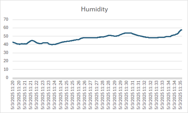
Sample Data


Appendices
You can find our code here.


Comments